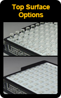

Surface Mat Styles
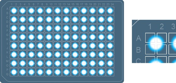
Array top surfaces come in two styles, Lens Mat and Diffuse Mat.
Array top surfaces come in two styles, Lens Mat and Diffuse Mat.
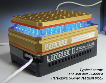
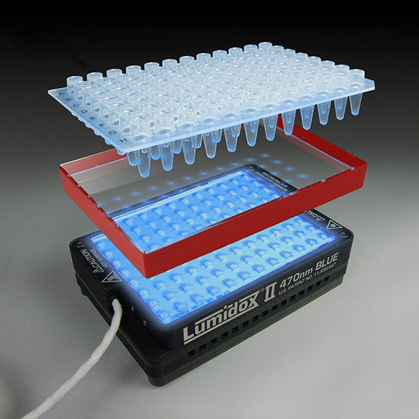
Lens Mat Surface
- Ultra-clear, molded to fit into the holes of a Para-dox® Reaction Block
- Captures nearly all light emitted by the array’s LEDs and directs it into the vials in the reaction block
- Chemically inert silicone

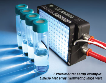
Diffuse Mat Surface
- Flat surface, making for easy pairing with SLAS footprint apparatus
- Can be used for niche applications such as illuminating cell culture flasks, reservoir plates, large scale containers, etc.
- Chemically inert silicone
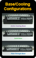
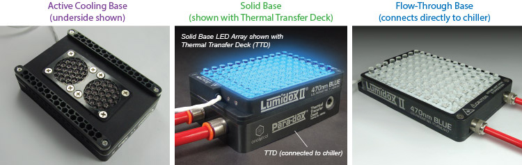
About Array Cooling and Base Options
Lumidox® II LED Arrays can generate a considerable amount of heat at any output stage and therefore need to be cooled. Both Lens Mat and Diffuse Mat style arrays are available with an Active Cooling base, Solid base or Flow-Through base. Each has it’s own specific way of cooling the LEDs in the array and can affect different application situations.
Flow-Through Base:
Note: Flow-through base LED arrays can only be used with an independent, dedicated recirculating chiller circuit. They cannot be daisy chained with any other hardware.
 Note: All LED arrays can operate in an incubator at 37ºC, 95% humidity
For added protection, each device has a built-in thermal cutoff switch that, in case of overheating, will automatically shut down the unit. The trip temperature for Solid Base and Flow-thru Base Arrays is 95°C, and will reset when cooled to 65°C. Active Cooling Base Arrays will shut down if their temperature exceeds 75°C. They will reset once they have cooled to 45°C.
Note: Active Cooling Base arrays are not compatible with strong magnetic fields such as those found in most tumble stirrers due to interference with the cooling fans.
Lumidox® II LED Arrays can generate a considerable amount of heat at any output stage and therefore need to be cooled. Both Lens Mat and Diffuse Mat style arrays are available with an Active Cooling base, Solid base or Flow-Through base. Each has it’s own specific way of cooling the LEDs in the array and can affect different application situations.
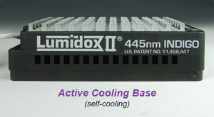
Active Cooling Base:
- Self-cooling, no external cooling source required
- Fully conforms to SLAS/ANSI standard dimensions
- Ideal for lower output applications like cell culture and PCR work (may require special adapter)
- Not compatible with tumble stirrers or devices that generate powerful magnetic fields
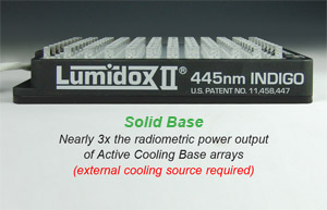
Solid Base:
- External cooling source is required (see Thermal Transfer Deck)
- A Thermal Transfer Deck (TTD) is recommended and can be attached to the base when used in conjunction with a recirculating chiller. The TTD can be removed if using a different cooling source, such as a cooling bay
- Fully conforms to SLAS/ANSI standards and can be used with cooling baths, plates, or other cooling chamber (if NOT being used with our Thermal Transfer Deck and recirculating liquid chiller)
- Ideal for applications requiring high output - up to nearly 3x more radiometric power output than Active Base arrays
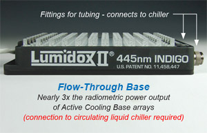
Flow-Through Base:
- Provides the most optimal cooling efficiency for LED arrays
- Direct connection to recirculating liquid chiller (required). Cooled liquid flows through the array base itself (no need for Thermal Transfer Deck)
- Ideal for applications requiring high output - up to nearly 3x more radiometric power output than Active Base arrays
- Light Weight – improved usability with orbital shakers due to lower overall mass
- Shorter overall height than active base array – offers improved compatibility with tumble stirrers (less distance between stirrer and sample)
Note: Flow-through base LED arrays can only be used with an independent, dedicated recirculating chiller circuit. They cannot be daisy chained with any other hardware.
For added protection, each device has a built-in thermal cutoff switch that, in case of overheating, will automatically shut down the unit. The trip temperature for Solid Base and Flow-thru Base Arrays is 95°C, and will reset when cooled to 65°C. Active Cooling Base Arrays will shut down if their temperature exceeds 75°C. They will reset once they have cooled to 45°C.
Note: Active Cooling Base arrays are not compatible with strong magnetic fields such as those found in most tumble stirrers due to interference with the cooling fans.
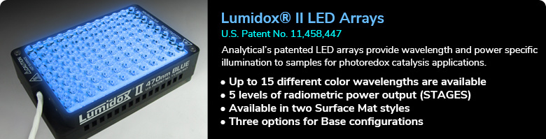
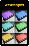
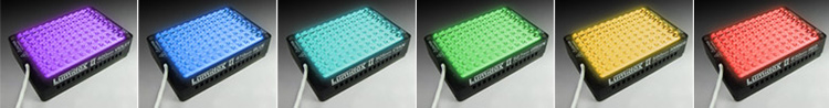
Lumidox II LED Arrays are available in up to 15 wavelengths*:
365nm UV
375nm UV
385nm UV
395nm UV
405nm UV
420nm-Violet
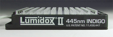
445nm-Indigo
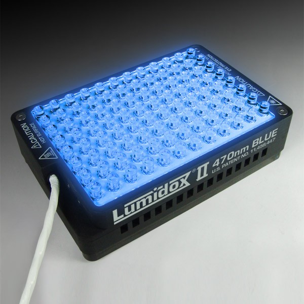
470nm-Blue
505nm-Cyan
527nm-Green
590nm-Amber
630nm-Red
660nm-Deep Red
730nm-IR Infrared
810nm-IR Infrared
White
Note: LUM2CON controller is required to power LED arrays.375nm UV
385nm UV
395nm UV
405nm UV
420nm-Violet
445nm-Indigo
470nm-Blue
505nm-Cyan
527nm-Green
590nm-Amber
630nm-Red
660nm-Deep Red
730nm-IR Infrared
810nm-IR Infrared
White
* Most LED arrays (excluding Discovery) are wavelength-specific - only one wavelength per device
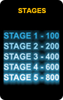
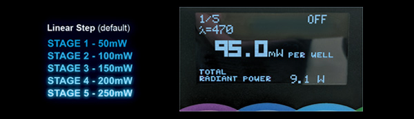
LED Output STAGES
By default, Lumidox II LED arrays and LumLamps (not the controller*) are factory calibrated with 5 discrete linearly stepped output STAGES. STAGE 1 output is the least radiometric power while STAGE 5 output is the most. STAGES are calibrated to the nearest whole number of radiant flux, and displayed in milliwatts (mW).
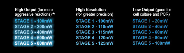
Custom Tuned STAGES
Analytical offers custom tuned stages to meet specific and unique requirements. These can range from maximum light output to low output to tight resolution. *NOTE: STAGE settings are stored on each individual Lumidox® II peripheral device (LED Array or Lumlamp), and are not tunable via the controller. Custom STAGE settings can only be calibrated by Analytical Sales and Services prior to shipment. Please contact Analytical before ordering.
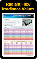
See also: Lumidox®II Radiant Flux and Irradiance Values for LED ArraysBy default, Lumidox II LED arrays and LumLamps (not the controller*) are factory calibrated with 5 discrete linearly stepped output STAGES. STAGE 1 output is the least radiometric power while STAGE 5 output is the most. STAGES are calibrated to the nearest whole number of radiant flux, and displayed in milliwatts (mW).
Custom Tuned STAGES
Analytical offers custom tuned stages to meet specific and unique requirements. These can range from maximum light output to low output to tight resolution. *NOTE: STAGE settings are stored on each individual Lumidox® II peripheral device (LED Array or Lumlamp), and are not tunable via the controller. Custom STAGE settings can only be calibrated by Analytical Sales and Services prior to shipment. Please contact Analytical before ordering.
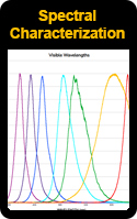
Typical Spectral Characterization
UV Wavelengths
Visible Wavelengths
Broad Spectrum Wavelengths
Infrared Wavelengths
Transparent orange acrylic is excellent for blocking UV and blue (365 to 470nm) light. We recommend 1/8" thick material. 
Yes. Stagnant VOC vapors will permeate the LEDs, potentially leading to discoloration and/or damage, which may be reversible. If sufficient ventilation for VOCs cannot be provided, please periodically run your array on stage 5 for 2-3 hours with a fan blowing on the LEDs to completely burn away all the VOCs and revert the array back to its original state. See Product Note: Lumidox® II LED Arrays and VOCs
Yes, please contact engineering@analytical-sales.com for assistance. We will be able to walk you through the process. Please be sure to navigate to the "Additional Information" tab on our Lumidox controller webpage ahead of time, and download the firmware update files. Within that folder will be an executable file named GUI5R7529.exe. This is the GUI that we will utilize to make the changes to the array. Please contact your IT department if the file is blocked. You will also require the USB Cable that was provided with your controller.
We do provide some Python scripts for convenience. These downloadable files can be found under the “Additional Information” tab of the LUM2CON product page. Please note that the use of scripts for the Lumidox controller is experimental and not a supported commercial feature.
Our Lumidox units are easy to integrate with automation systems, as they were designed with this intention in mind.
The serial commands themselves plus some sample Python files can be downloaded from the "Additional Information" tab on our Lumidox controller page. Note that these features are currently experimental, and not yet officially supported.
The available commands in Lumidox Controller II – Serial Commands guide should cover all of the tasks needed to integrate and fire the units with your automation platform. Analytical also has "extension" cord sets available to extend the distance the array can be from the controller.
Collapse
LED Arrays for TCR
96-Position, Single Wavelength LED Arrays
U.S. Patent No. 11,458,447 Use with Para-dox® Standard 96-Position Aluminum Reaction Blocks for photoredox catalysis applications.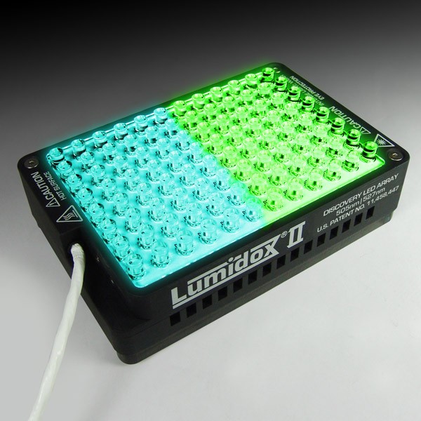
96-Position Discovery LED Arrays
U.S. Patent No. 11,458,447 Lumidox® II Discovery LED Arrays for screening offer researchers an economical and time-saving way to evaluate all of the wavelengths that the...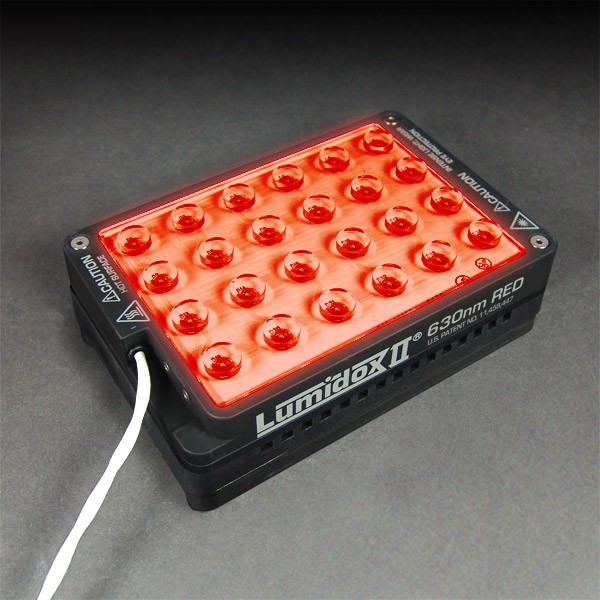
24-Position, 18mm Spacing LED Arrays
U.S. Patent No. 11,458,447 Use with Para-dox® 24-Position Aluminum Reaction Blocks with 18mm Spacing for photoredox catalysis applications.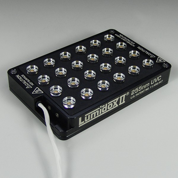
24-Position, 255nm-UVC Arrays for Quartz Vials
Our 255nm UVC wavelength LED Array opens the door to exciting new applications—from high-energy photochemistry to polymer resin curing and surface disinfection—making...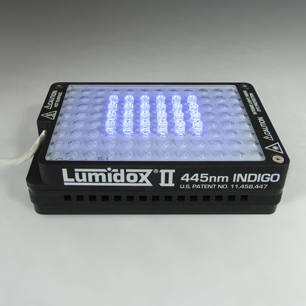
24-Position, 9mm Spacing LED Arrays
U.S. Patent No. 11,458,447 Use with Para-dox® 24-Position Aluminum Reaction Blocks with 9mm Spacing for photoredox catalysis applications, or HTe-Chem Assemblies for...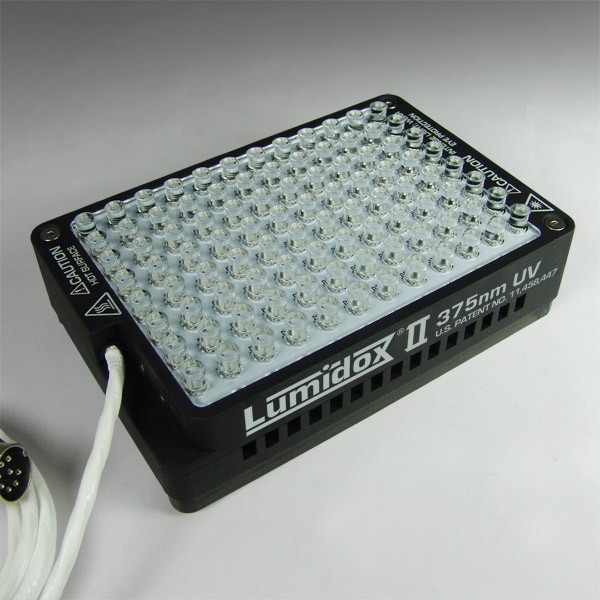
LED Arrays for Cell/Bio Work
Cell culture or biological applications push the limits of the lower end of the LEDs’ output range. Our novel arming sequence facilitates this by slowly increasing the...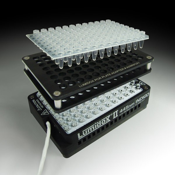
PCR Plate Adapters
If your workflow involves the use PCR plates, then Lumidox® II Lens Mat Arrays are perfectly suited for your research. Lumidox II Arrays generate highly precise,...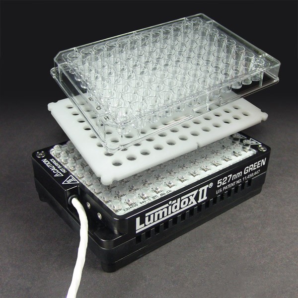
Cell Culture Plate Alignment Spacers
Glass Block for Light Reduction (PCR, Cell Culture)
Use to reduce the amount of light intensity delivered to your samples by increasing the distance between the samples and the light source (LED array). Place the Glass Block...